

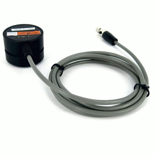

Optical digital sensor “TKA-DOTS”
PRICE:
PRICE:
27360 руб.
TU 26.51.53-006-16796024-2020.
The sensor is designed to measure (depending on the type of sensor):
- irradiation in the spectral regions:
- 315 – 400 nm (UV-A zone),
- 280 – 315 nm (UV-B zone),
- 280 – 400 nm (UV-A + B zone),
- 200 – 280 nm (UV-C zone),
- illumination in the visible region of the spectrum [lx];
- brightness in the visible spectrum [cd / m 2 ]
Operating conditions: from -30 to +60 ° С.
Information output on UART.
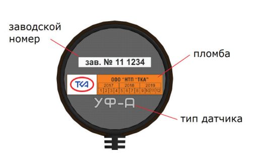
Supplied factory calibrated.
Terms of delivery 100% prepayment.
Production time up to 30 working days after payment.


- Description
- Appointment
- Application area
- Design and operation
Description
| Measured value dynamic range | 1.00 ÷ 1,000,000 |
| Graduation error, no more | ± (3.0 ÷ 5.0)% |
| The limits of the additional relative error of the device when measuring optical quantities, due to the change in the sensitivity of the photometric head when the air temperature in the measurement zone changes by every 10 ° С in the range from -30 ° С to 15 ° С and from + 25 ° С to 60 ° С | ± 3.0% |
| Dimension of the measured value depending on the type of sensor: Irradiance Illumination Brightness |
mW / m 2 lux cd / m 2 |
| Duration of a single measurement | 2 ms |
| Angular characteristic of the sensor sensitivity depending on the type * | |
| Irradiance level 1, not less | ± 10.0 ° |
| Illumination | cosine |
| Brightness level 1, not less | ± 12.5 ° |
| Performance parameters | |
| UART interface operating voltage | 3 in |
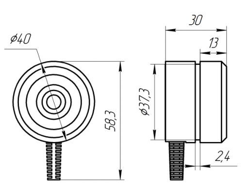
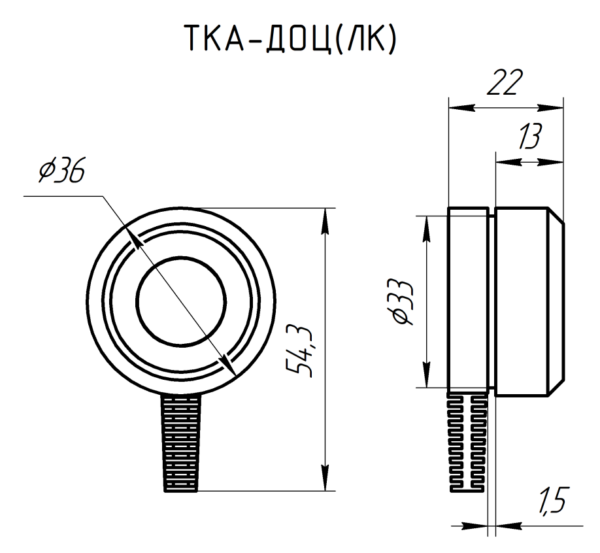
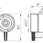
| Overall dimensions of the sensor | Ø40 x 30 mm |
| Length of cable | 1.2 m |
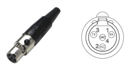
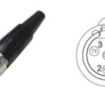
| Connector type | 4-pin mini XLR |
| Weight, no more | 100 g |
| Ambient temperature | from -30 to +60 ° C |
| Relative air humidity at an ambient temperature of +25 ° С |
up to 98% |
| Atmospheric pressure range | 80 ÷ 110 kPa |
The sensor is designed to measure (depending on the type of sensor) irradiance in the spectral regions:
- 315 – 400 nm (UV-A zone),
- 280 – 315 nm (UV-B zone),
- 280 – 400 nm (UV-A + B zone),
- 200 – 280 nm (UV-C zone),
illumination or brightness in the visible region of the spectrum.
Execution of work under sanitary and technical supervision in residential and industrial premises, certification of workplaces and other areas of activity.
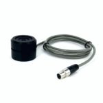
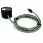
Structurally, the sensor is made in the form of a single unit with a cable for power connection and data exchange.
The principle of operation of the sensor consists in converting optical radiation into an electrical signal by a photodetector with subsequent transmission of the measurement result via a wired interface in the form of a digital code.
A 2.4 mm wide groove is made in the sensor body along the diameter for attaching the sensor to a tripod mount (optional) or to the equipment available to the consumer.
For operation, the sensor can be connected to the Information Processing Unit (YUSUK.10.0002 PU “TKA-UFD”, supplied separately) or to any device with appropriate characteristics.
Data exchange is carried out using the UART protocol. Connection parameters:
- Baud rate 115200;
- Data bits 8;
- Stop bits 1;
- Parity – none.

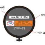
Connector and Pin Designation (Front View)

Position of the photometric plane depending on the spectral range of the sensor
Irradiance sensor Place the
sensor with the photometric plane at the measuring point towards the object being measured. The photometric plane depends on the spectral range of the irradiance sensor. Make sure that no shadow from the operator taking measurements, as well as the shadow from temporarily located foreign objects, falls on the input diaphragm. The angular dimension of the measured radiation source, visible from the measuring point, should not exceed ± 10 °.
Light sensor.
The photometric plane is the outer face of the diffuser, while it coincides with the outer face of the sensor body. The housing design provides an angular cosine response. To take measurements, place the sensor with the photometric plane at the measuring point. Make sure the
illumination is uniform across the sensor entrance window.
Brightness sensor.
This type of sensor is designed to measure the brightness of extended self-luminous objects by the overhead method. To measure, place the sensor close to the object to be
measured without gaps. In this case, the brightness of the object in the field of view of the device should be uniform.